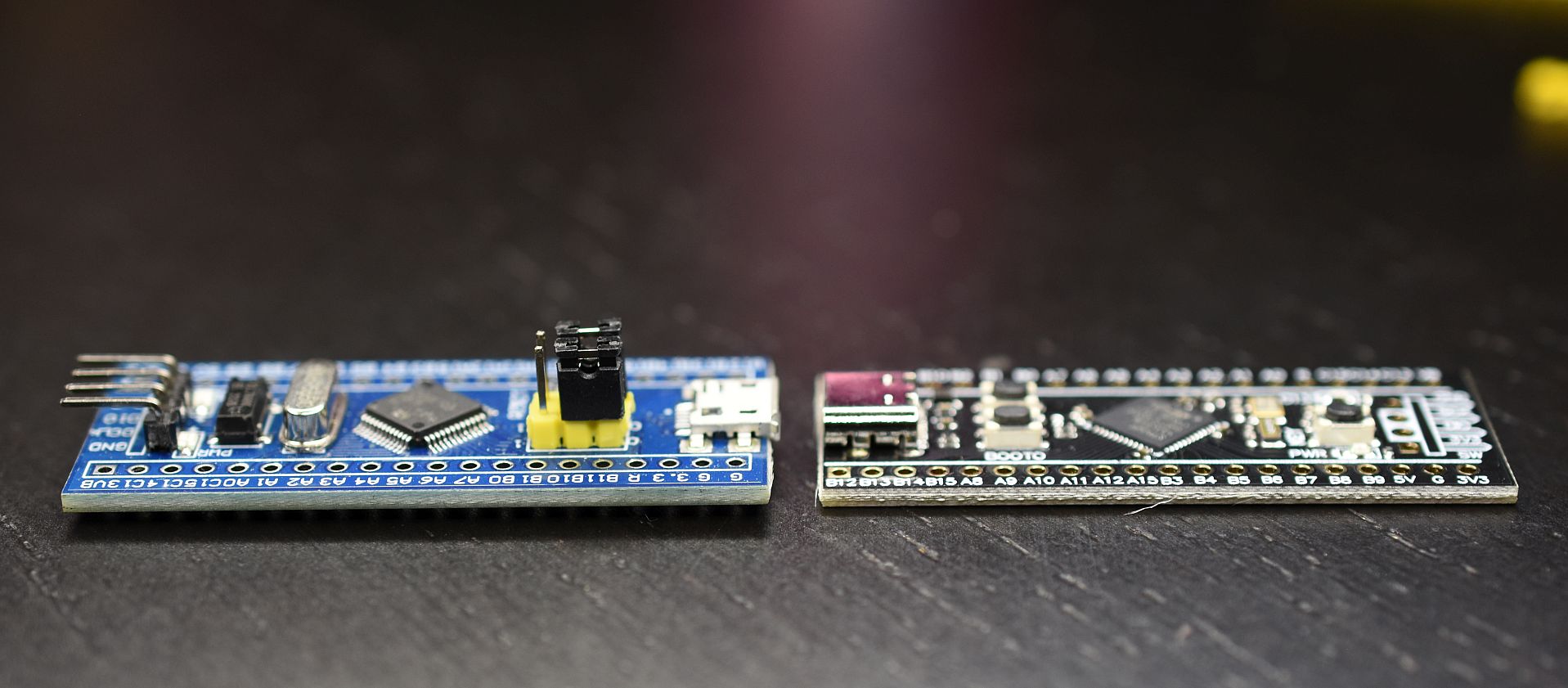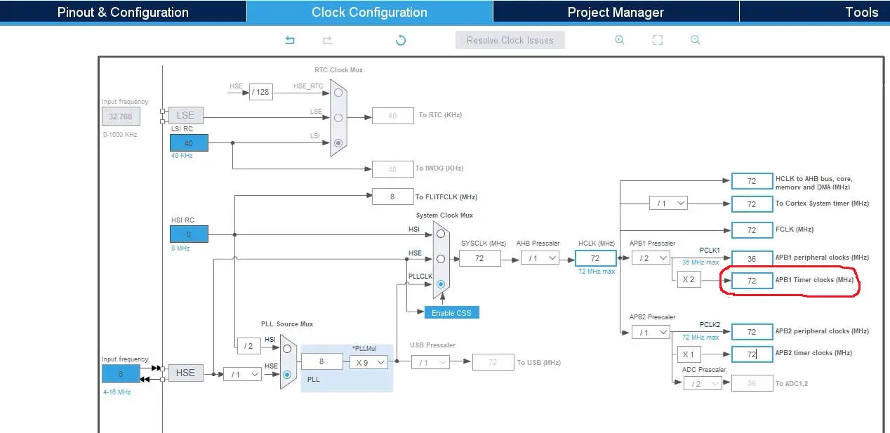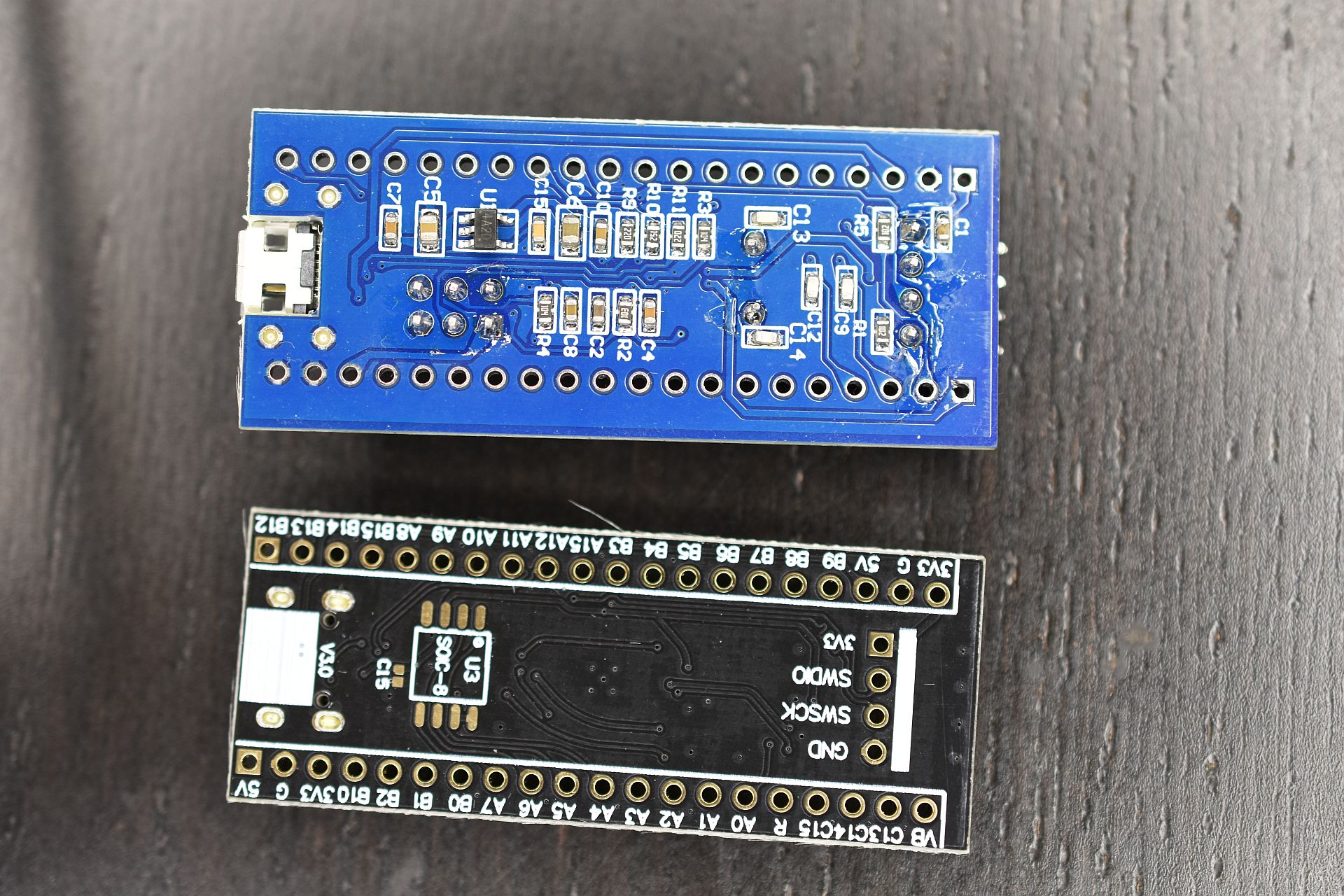

This board uses cylinder oscillators also for HSE clock. CrystalĪll the other C8 boards are using a traditional 8 MHz High Speed External oscillator and a cylinder oscillator for the Low Speed External signal (32.768 kHz) for the internal Real-Time Clock. The physical Reset button has to be used before a debugging session can start. Even when the NRST (Negative Reset) is in the SWD header, it was not working with ST-LINK V2 devices. This board can be inserted on a standard breadboard. SWD pins are available for quick connections in a 5-pin header. There is green power LED and no other LEDs. In addition of the rest button, there is Boot0 jumper. The size (0.72in x 1.00in x 2.44) and low weight (8g) allows its usage in some flying applications.
#SMT32F103 BLUE PILL SCHEMATIC SERIAL#
In center of the board, there is a 8-pin header for boot loading through serial connection. There is a separate 4-pin SWD header, but its labeling is nonstandard (TCK and TMS). This board can not be inserted on a standard breadboard. SWD pins are available for quick connections in a large standard JTAG connector. In addition of the red power LED with label D1, there is another red LED with label D2 connected to PD2. The weight (18g) limits its usage in some flying applications. The size (0.46in x 1.78in x 2.47) allow a lot of connection pins. Instead, it can be inserted on two breadboards for prototyping.


In addition of the yellow power LED, there is a yellow user LED (PC13). The boot jumpers are in same positions as in Blue Pill board, Boot0 is close to the processor and Boot1 is close to GND pin. The weight (15g) limits its usage in some flying applications. The size (0.51in x 1.44in x 2.90) allow a lot of connection pins. There is a 8-pin female connector for (TBD). There is a 6-pin header for GND, 3V3, and 5V. In addition of the green power LED, there is a green user LED (PC13). In addition of the rest button, there is a user button (PA0) and Boot0 jumper. The weight (13g) limits its usage in some flying applications. The size (0.45in x 1.66in x 2.18in) allow a lot of connection pins.

Although the NRST signal is not included to enable ST-Link reset. SWD pins are available for quick connections. Schematicsĭue to high volumes, this is the most cost effective F103 board. In addition of the red power LED, there is a green user LED (PC13). In addition of the reset button, there are jumpers for Boot0 and Boot1 selections. When size (0.45in x 0.89in x 2.27in) or weight (6g) is a critical factor, this is a reasonable solution. BackĬomments Small Size with High Performance The upper yellow jumper is Boot0 and the lower, next to Reset button, is Boot1. The labels on this board are not very good. Typical nick names of these boards refer them by their color, blue and red. There are several variants of this very low cost board.


 0 kommentar(er)
